Список форумов Ремонт бытовой техники и електронники Ремонт бытовой техники и электроники
 
  Файло-обменникФайлы    ПрошивкиПрошивки   ПродажаПродажа   ЛитератураЛитература   СтатьиСтатьи 
Прошивки
Меню сайта

Наши базы

Форма входа

Найти прошивку
 Искать у Нас 
Помощник


 Искать по всему сайту 

Реклама

Найти DataSheet
 Искать на Doc.chipfind 


 Искать на Alldatasheet 


На Datasheetarchive


 Поиск в PDF по Google 

Опознать SMD
 SMD codebook Сахара 

Друзья сайта


REM-TV

Сейчас на сайте
Онлайн всего: 173
Гостей: 124
Пользователей: 49
diltuk, Duba73, vadim08, Sanek3711, YYS111, Вова_Ор, alkirushin, Jonibek7272, remont71, hrip, Вано, Fotik, JonBlack, ahaaha, canzas, Level9, super72, rublix, HyperShop, procs, Niki2109, Bunyod, alekss0505, Volich, franzz79, Виталий2017, serghei65, teror, TSOP, machenist, sergio998, greyfills, mister_76, navigator7777, waleedhsaneen, larisalotyreva, Vigen, Vovodjan36, мастер2000, svch_, Dmitry1408, gadji56, Codepwr, zzz555, PAY, nach72, sven76, Anton9210

Top 20 Uploaders

Партнёры проекта


Приветствую Вас, Гость · RSS 15.06.2025, 08:40:43

Главная » Прошивки » Прочие » Прочее


Philips GC8641 Шасси (Main Board): florida control board v3

Паровая станция Philips


фото 1 , фото 2 , фото 3 , фото 4 , фото 5
Чтобы скачать данный файл, нужно Зарегистрироваться и пройти Тест
Раздел: Прочие
Категория: Прочее
Добавил: kir315
Список микросхем в архиве: pic16f1936
CPU/MCU: pic16f1936
Источник прошивки: Проверена лично перепрошивкой
Могут скачать: Все Участники
Размер файла: 0.01Mb
Загрузок:
Прошивка добавлена: 04.04.2019 в 11:55:26
Информация ! Если прошивка находится не на нашем сервере, а на сторонних сайтах (ЯндексДиск, ГуглДиск и т.д) , сообщите в этой теме , укажите ссылку на этот материал.

Всего комментариев: 6
#1   (26.04.2020 12:59:22) [Материал]
  
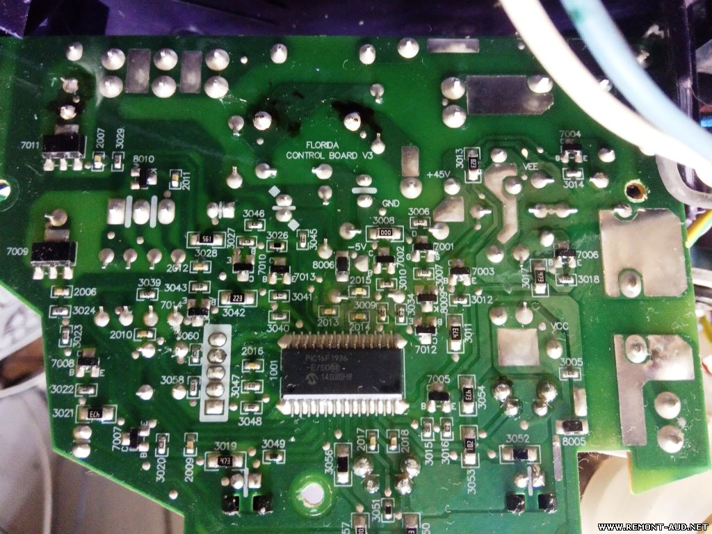
If anyone is interested, I have more information. I have disassembled the logic and have added lots of comments in an attempt to understand what it is doing. I have some partial schematics of the control board that I have traced-out (mainly to identify the I/O). Unfortunately, the logic has been written in a higher-level language, and was obviously structured very horribly to begin with. I am not sure I will pursue this problem (the problem is that the pump will not run even though the PCB circuitry seems to be working).


#2   (04.05.2020 13:31:38) [Материал]
  
Hi! I have some problem as you posted here. In my PCB, pump semistor was be broken, after replacement, pump would't start on power on( EEPROM clearing need?)


#3   (05.05.2020 19:42:49) [Материал]
  
Hello , I'm starting in this profession, I have 5 volts that appear from the capacitor and the resistance, but I don't understand how the 45 volts appear, you can explain to me, how this 45 voltage appears, thanks


#4   (05.05.2020 19:43:52) [Материал]
  
Hello good, I'm starting in this profession, you can have the 5 volts that appear from the capacitor and the resistance, I don't understand how the 45 volts appear, you can explain to me, how this 45 volt voltage appears vopros


#5   (28.02.2022 21:09:03) [Материал]
  
45 Вольт получается путем выпрямления сетевого напряжения с делителя на резисторах.


#6   (28.02.2022 21:14:51) [Материал]
  
Диод на обратной стороне в районе слова "control".


Добавлять комментарии могут только зарегистрированные пользователи.
[ Регистрация | Вход ]